
Guides · CombiSteel Knowledge Hub
CombiSteel Pizzeria Hot Line Layout Guide: Oven 7485.0020, Hood 7333.1145
Learn how to plan a pizza-side hot line using verified dimensions and manual constraints for the CombiSteel 7485.0020 gas deck oven and 7333.1145 wall-mounted hood, with a practical straight-line example for briefing designers and installers.
In this guide
You are laying out a pizza-side hot line where a gas deck oven, canopy extraction, and a simple make → bake → hold flow all compete for the same wall space. This guide shows how to position the CombiSteel gas pizza oven 7485.0020 and a CombiSteel wall-mounted hood 7333.1145 using only verified footprints and manufacturer constraints, so you can brief your designer and installers accurately.
You will work through what matters on site: the oven’s true station footprint, what access you should not block (including service-side access), what the oven manual requires for hood, flue and combustion air planning, and what it means that the hood is supplied without a controller or engine. Pizza holding stays generic and layout-led.
Introduction to pizza-side hot line planning
Pizza-side hot line planning is the layout and services coordination for the part of your kitchen where pizza production creates the most heat, footfall and pressure. In a CombiSteel-led setup, that usually means coordinating a gas deck oven position with canopy extraction, safe access for loading and unloading, and enough space to connect and service the appliance.
In Irish fit-outs, dimensions tell you the footprint, but they do not confirm extraction design or compliance. The CombiSteel oven manual is clear that installation work such as positioning, electrical connection, gas and flue connections, adjustments and checks must be carried out by a qualified technician under local rules (CombiSteel Manual 7485.0010-0015-0020 (covers 7485.0020)). Treat this as layout coordination, not installation instruction.
What you are actually planning (make → bake → hold)
Most pizza lines fail for practical reasons: the door swing gets blocked, peels cross another person’s path, or “just one more bit of kit” creeps into the hot zone.
With a deck-oven station, you are planning three things at once:
- A clear working rhythm between make, oven mouth and pass.
- A defined high-heat zone that stays workable during service.
- A services and access plan that remains reachable after stainless and joinery go in.
Think in no-block zones, not just appliance widths. The oven manual notes it is advisable to leave space on the right-hand side to allow removal of the right panel if maintenance requires it (CombiSteel Manual 7485.0010-0015-0020).
Why extraction layout is part of the oven decision
For ovens covered by the 7485.0020 manual, the oven is described as a type “A” appliance. The manual states it must discharge combustion products through a suitable hood or similar device connected to a functioning flue, or directly to the exterior (CombiSteel Manual 7485.0010-0015-0020). It also states the room must be sufficiently aired, and gives a combustion-air requirement of 2 m³/h per kW of oven power, plus 35 m³/h for the room (CombiSteel Manual 7485.0010-0015-0020).
Those points do not size your fan for you, but they do tell you extraction and make-up air cannot be left until the end.
What a wall-mounted hood is and what it is not
A wall-mounted canopy like CombiSteel 7333.1145 gives you a physical capture area over the oven station and is supplied with lighting and filters, based on the product listing (Caterboss listing for CombiSteel extractor hood 7333.1145). It is listed as stainless steel 430, with three filters sized 495 × 495 × 25 mm and an integrated tap for drainage.
What it does not give you on its own is a complete extraction system. The same listing states Controller: No and Engine: No.
So, at planning stage, you are scoping:
- Where the fan will go, how it will be controlled, and what duct route is buildable.
- How make-up air will be handled so the kitchen is not starved of air.
- Ongoing access for filter removal and drainage.
Key checks to lock down before you start drawing joinery
- Plan the oven station as a serviced appliance location, not a fixed cabinet run. The oven manual explicitly anticipates access for maintenance, including right-side panel removal if needed (CombiSteel Manual 7485.0010-0015-0020).
- Treat combustion air and fume disposal as design requirements. The manual specifies 2 m³/h per kW plus 35 m³/h for the room (CombiSteel Manual 7485.0010-0015-0020).
- Keep neighbouring equipment out of the oven access areas and canopy capture zone. If the canopy or service panels are hard to reach on day one, they will be worse six months in.
Positioning the CombiSteel Gas Pizza Oven 7485.0020
Treat the CombiSteel 7485.0020 as a fixed station planned around extraction and flue routing first. The user manual is clear that positioning, electrical connection, gas and flue connections must be carried out by a qualified technician, and that the oven must be installed in technical rooms with appropriate ventilation and disposal of cooking fumes (CombiSteel Manual 7485.0010-0015-0020). In practice, you agree the oven location with whoever is designing and signing off the gas and ventilation.
Use the full footprint (plus access), not the deck size
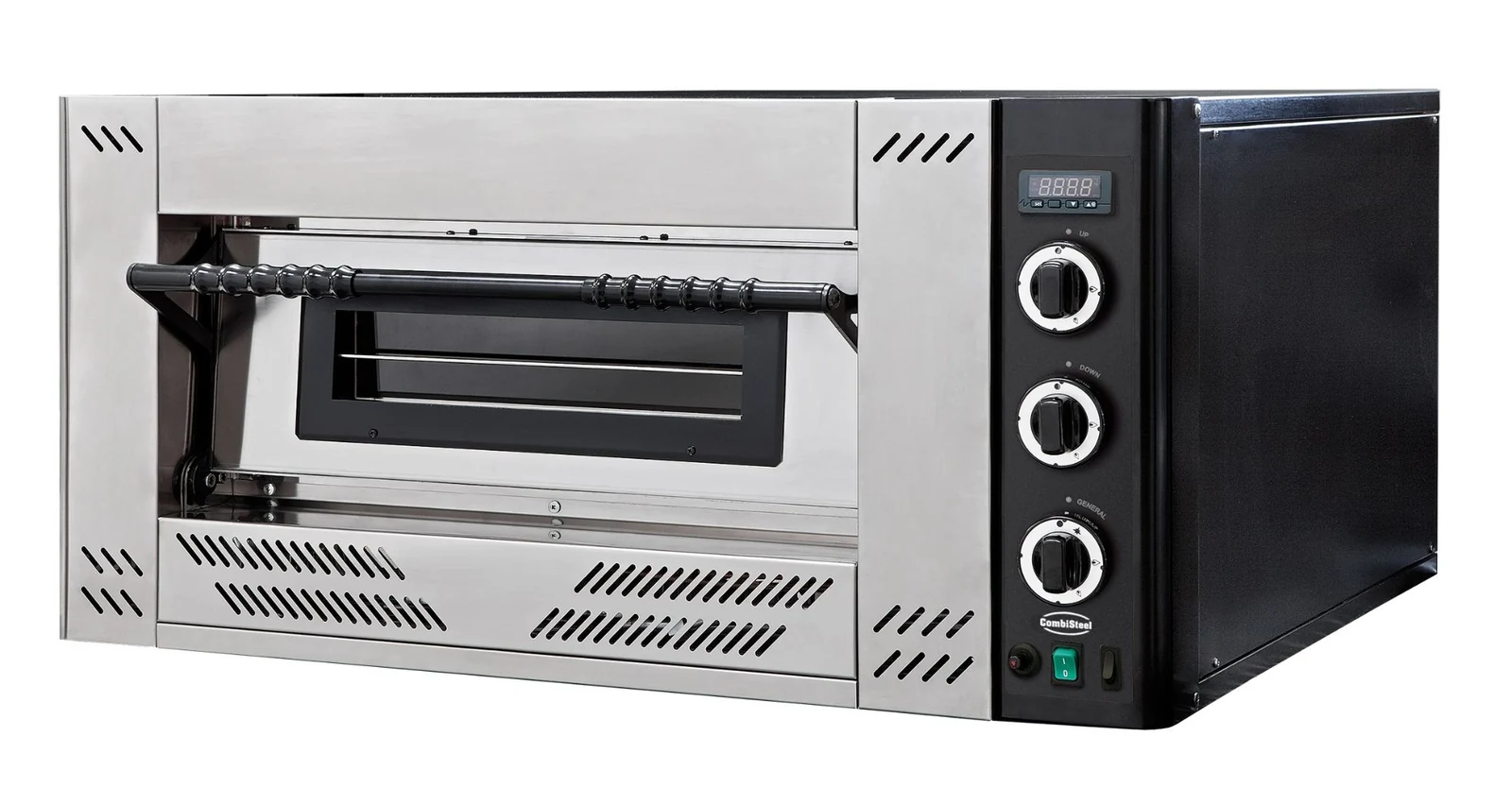
The 7485.0020 occupies more space than the baking deck suggests. Its external dimensions are listed as (H) 560 × (W) 1305 × (D) 1362 mm on the Caterboss listing for CombiSteel 7485.0020.
Start your layout with that footprint, then allow for:
- Clear working space in front of the door for loading and unloading.
- Service access where panels and connections may need to be reached.
The internal deck size (cavity 920 × 920 × 150 mm) helps with capacity planning, but it does not reduce what the oven blocks in the line.
What the manual wording means for where you can and cannot place it
The manual describes the oven as a type “A” gas appliance and states it must evacuate combustion products through a suitable hood or similar device connected to a flue in working order, or directly outside. It also states it should be installed in a sufficiently aired room (CombiSteel Manual 7485.0010-0015-0020).
Practically, this pushes you away from placing the oven where:
- A canopy cannot sit above it cleanly (bulkheads, shelving, passes, low ceilings).
- The duct and flue path becomes long, awkward, or hard to access later.
Access you should not block: right-hand panel, connection points, flue outlet
The manual notes it is advisable to leave space at the right (DX) side of the oven to allow removal of the side panel for maintenance (CombiSteel Manual 7485.0010-0015-0020). It also shows the oven has a gas predisposition connection point and a Ø150 mm flue (CombiSteel Manual 7485.0010-0015-0020). These are exactly the areas that get trapped when you butt tall units and fixed joinery tight to the oven.
When you set the line, keep these zones serviceable:
- Right-hand side: do not permanently trap the side panel behind fixed equipment if you expect the oven to be maintained in position.
- Connection points and flue route: avoid designing a sealed box around the oven where technicians cannot get to the connection areas and discharge path when the kitchen is operational.
Plan for combustion air, not just “a hood”
The manual gives a combustion-air requirement of 2 m³/h per kW of oven power, plus 35 m³/h for the room (CombiSteel Manual 7485.0010-0015-0020). In a tight unit, do not assume “a hood exists” equals “air is sorted”. Treat this as a design conversation with whoever is responsible for ventilation.
Ventilation and extraction requirements (what you can verify)
Start with what the oven manual actually states, then treat the CombiSteel hood as the canopy you can physically fit. Everything else, fan duty, duct route, discharge point and make-up air, has to be designed as a complete system for your site.
1) Manual constraints you need to design around
The manual covering 7485.0020 states:
- Installation operations including positioning, electrical connection, gas and flue connections, adjustments and controls must be executed by a qualified technician respecting local rules (CombiSteel Manual 7485.0010-0015-0020).
- The oven must be installed in technical rooms with appropriate ventilation and disposal of cooking fumes (CombiSteel Manual 7485.0010-0015-0020).
- As a type “A” appliance, combustion products must be evacuated through a suitable hood or similar device connected to a flue in working order, or directly to the exterior (CombiSteel Manual 7485.0010-0015-0020).
It also includes an explicit numeric statement under flue connection:
- “THE OVEN MUST BE INSTALLED WITH AT LEAST 0,50 METERS FROM HOOD, CHIMNEY, OR DIRECTLY OUTSIDE.” (CombiSteel Manual 7485.0010-0015-0020)
That line is important, but it is also ambiguous in geometry. The manual excerpt does not make clear whether “0,50 meters” is measured from the flue outlet to the hood, from the oven body to the hood, or along a specific flue arrangement. Do not convert it into a canopy overhang or mounting-height rule. Instead, flag it early to your ventilation and gas installer and ask them to confirm the correct interpretation for your set-out.
2) Use the 7333.1145 hood dimensions for space planning, not airflow sizing
For space planning, CombiSteel 1100 wall-mounted extractor hood 2000 (7333.1145) is listed at (W) 2000 × (D) 1100 × (H) 400 mm. It is listed as stainless steel 430, with three filters (3 × 495 × 495 × 25 mm), lighting, and an integrated tap.
What you cannot do from the sources provided is size the fan or claim compliance. No airflow duty, capture velocity or recommended fan selection is stated for 7333.1145.
Also note the footprint interaction: the oven depth is 1362 mm while the hood depth is 1100 mm. That does not mean the hood is wrong, but it does mean canopy position, mounting height and any forward overhang must be designed for your site. You cannot assume “hood footprint equals full oven footprint”.
The hood listing states Controller: No and Engine: No, so you are still specifying and supplying the fan, controls, ductwork and commissioning as part of the wider ventilation package.
If you need the manufacturer’s mechanical assembly document for the canopy hardware, use the listed download: CombiSteel assembly instructions for extractor hood.
3) Use the manual’s combustion-air figure as a minimum conversation, not a fan spec
The oven manual states 2 m³/h per kW of oven power, plus 35 m³/h for the room (CombiSteel Manual 7485.0010-0015-0020). The 7485.0020 is listed at 27 kW total gas output.
So, as a worked minimum for discussion:
- 2 × 27 = 54 m³/h
- 54 + 35 = 89 m³/h
Use 89 m³/h as a starting point to discuss combustion air and room ventilation with your engineer. It is not an extraction fan specification, and it does not account for heat load, cooking fumes, balancing supply and extract air, or discharge constraints.
Integration with other hot line equipment
Integrate your make table and any hot holding around the oven and canopy by treating the oven station as fixed. Build a one-way flow (make → bake → hold) and keep the areas the oven and hood need for safe use, ventilation and maintenance clear.
Fix the oven and hood as a no-block zone
Do not solve storage or landing-space problems by squeezing equipment into the oven station. The oven manual anticipates servicing, including right-side panel removal, and requires installation and connections to be carried out by a qualified technician (CombiSteel Manual 7485.0010-0015-0020).
Protect three things from day one:
- The operator zone at the oven mouth: keep the loading position clear.
- Service access: keep the right-hand side serviceable so the panel can be removed if needed.
- The canopy capture path and duct route: because the oven relies on a suitable hood or similar device, do not design fixed obstructions that compromise the capture zone or block future access.
Keep the make table upstream and avoid pinch points at the door
Put the make table immediately before the oven in the direction of travel (make → bake). Aim for a clean handoff where the operator can dress at the table, pivot to load, and step away again without being pinned between the oven door and the next piece of equipment.
Put hot holding downstream, but keep it out of the access and capture zones
Hot holding works best after the oven (bake → hold) so finished pizzas move away from the loading position.
This guide is not tied to a specific holding cabinet model or footprint in the evidence set, so keep “hold” generic at layout stage. For holding options and trade-offs, use the dedicated guide: pizza holding hot cabinets for pizzeria line setup.
Hypothetical layout example
Your final layout depends on room volume, extraction design, and how staff move during service. At planning stage, you can build a first-pass straight line using verified footprints, then hand that sketch to a qualified gas and ventilation professional to confirm set-out, duct route, flue arrangement and local compliance (CombiSteel Manual 7485.0010-0015-0020).
Worked straight-line example (make → bake → hold) using only verified footprints
Assumptions (explicitly hypothetical): one single-deck oven, one wall-mounted canopy centred on the station, and generic hot holding immediately after bake.
Verified dimensions:
- Oven body: (W) 1305 × (D) 1362 mm
- Hood body: (W) 2000 × (D) 1100 mm
Layout sketch (straight line):
- Make zone (prep and dress): place the make table first so the operator can dress and load without crossing the person working the pass.
- Bake zone (oven station under canopy): centre the oven width (1305 mm) under the hood width (2000 mm) so you have canopy width spare either side.
- Hold zone (generic hot holding and pass): position holding after the oven, but keep it movable on the drawing until your ventilation designer confirms what can sit near the capture zone and duct route.
Depth note you need to resolve with your designer: the oven is deeper (1362 mm) than the hood (1100 mm). Canopy position, any forward overhang, and mounting height must be set by the ventilation designer and installer. This guide cannot define those dimensions.
If you want to stress-test the flow (rather than the services), cross-check this sequencing approach in planning a pizzeria work line.
Translating “9 × Ø30 cm” and a 920 × 920 mm deck into the station you need
The 7485.0020 listing gives two useful capacity clues:
- Baking cavity: 920 × 920 × 150 mm
- Rated load: 9 pizzas at Ø30 cm per load
That tells you what fits per bake, not what you will get per hour in a real service. For layout planning, the consequence is simple: allow landing space and a safe stance at the oven mouth, because you are handling multiple pizzas in and out.
Also note the manual warning: for continuous use, do not exceed 350°C (CombiSteel Manual 7485.0010-0015-0020). The product listing still shows a thermostat range up to 0/+450°C. For layout, the takeaway is that steady working rhythm matters. If you are constantly rushing the oven, congestion at the mouth and pass gets worse.
Mark the no-block zones without inventing clearances
The manual states the oven must be positioned according to minimum measurements shown in FIG.5, and it advises leaving space at the right-hand side (DX) to facilitate panel removal for maintenance (CombiSteel Manual 7485.0010-0015-0020). This guide is not reproducing FIG.5, so use the manual and your installer’s set-out.
What you can safely mark on your sketch from the text:
- In front of the door: the manual warns to maintain a safety distance when opening the door with the oven on due to direct heat (CombiSteel Manual 7485.0010-0015-0020). Do not place fixed obstacles where staff must stand to load and unload.
- Right-hand side access: keep it serviceable so the side panel can be removed if needed (CombiSteel Manual 7485.0010-0015-0020).
- Canopy capture and flue route: because the oven is type “A” and requires evacuation via a hood or similar device, keep the canopy zone and the route to flue or outside discharge clear on the plan.
Next step: sanity-check your oven and extraction set-out
Before you lock in joinery, sanity-check the fixed points: the oven footprint, the hood footprint, and what space you are leaving for duct route, combustion air and future access. Then bring the manual constraints into the installer conversation early, including the manual’s “0,50 meters” installation statement and its need for interpretation on your site (CombiSteel Manual 7485.0010-0015-0020).
For the canopy product spec, use CombiSteel 1100 wall-mounted extractor hood 2000 (7333.1145) as your reference point when you are coordinating stainless, wall space, and service access.